


Carbon fibre sleeves for high-speed electric motors
Contents |
[edit] Introduction
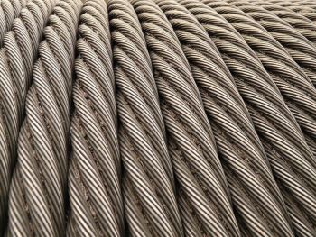
A carbon fibre sleeve is a composite structural component fitted around the permanent magnet assembly of a high-speed permanent magnet electric motor rotor. Its primary function is to retain the magnets against the centrifugal forces generated during operation while maintaining their position relative to the shaft over the motor's operating speed and temperature range.
At relatively low rotational speeds, adhesive bonding between the magnets and the rotor is generally sufficient. However, as rotational speed increases, the centrifugal forces acting on the magnets rise with the square of the rotational velocity. In many high-speed motors operating above approximately 30,000 rpm, adhesive bonding alone is insufficient, and an external structural sleeve is required to provide mechanical containment.
Carbon fibre composites are widely used for this application because they combine high specific stiffness and high specific strength with relatively low density. Compared with metallic sleeves, they can provide equivalent containment while adding less rotating mass and allowing a thinner sleeve wall. This helps maintain the air gap between the rotor and stator, which is important for electromagnetic performance and motor efficiency.
The thermal behaviour of carbon fibre composites is also advantageous. Although thermal expansion depends on fibre orientation and laminate construction, carbon fibre composites generally exhibit considerably lower thermal expansion than steel in the fibre direction, improving dimensional stability over repeated thermal cycles.
[edit] Mechanical function
Permanent magnets mounted on the outer surface of a high-speed rotor experience outward centrifugal forces during operation. The magnitude of these forces increases in proportion to the square of rotational speed, meaning that doubling the rotational speed results in approximately four times the centrifugal loading.
The carbon fibre sleeve applies radial compressive contact pressure to the magnet assembly through an interference fit between the sleeve bore and the outer diameter of the magnets. This compressive stress is commonly referred to as pre-load.
As rotor speed increases, centrifugal loading progressively reduces the compressive stress acting on the magnets. The sleeve is designed so that sufficient compressive contact pressure is maintained throughout the motor's rated operating range, preventing magnet movement or separation from the rotor.
Determining the correct interference fit requires detailed structural analysis because the resulting stresses depend on component geometry, material properties and operating temperature. Finite element analysis is commonly used to optimise sleeve thickness, laminate construction and interference dimensions.
[edit] Materials and manufacture
Carbon fibre sleeves are typically manufactured using high-strength carbon fibres within a thermosetting polymer matrix, most commonly epoxy resin. Fibre orientation, resin content and laminate quality all influence the mechanical behaviour of the finished component.
Several manufacturing methods are used depending on production volume, dimensional requirements and motor design.
[edit] Interference-fit sleeves
A composite tube is manufactured separately before being pressed onto the rotor assembly. The interference fit generates the required contact pressure.
This method can produce high retention forces but requires extremely accurate dimensional control. Unlike metals, carbon fibre composites exhibit limited plastic deformation, so excessive interference may cause cracking during assembly.
[edit] Filament winding
Continuous carbon fibre tow is wound directly onto the rotor under controlled tension before curing. The winding process produces both the required wall thickness and the compressive stresses necessary for magnet retention.
Filament winding is well suited to cylindrical components but requires careful control of winding tension to achieve consistent mechanical properties and dimensional accuracy.
[edit] Tape placement
Pre-impregnated carbon fibre tape is applied in successive layers under controlled temperature and pressure.
Automated tape placement offers greater control of fibre orientation, laminate thickness and consolidation than conventional winding methods and is often used where particularly demanding tolerances are required.
[edit] Dimensional accuracy
Dimensional accuracy is one of the principal engineering challenges in manufacturing carbon fibre sleeves.
The interference fit between the sleeve and the magnet assembly determines the contact pressure generated after assembly. Small dimensional variations can significantly affect this pressure. Insufficient interference may allow magnets to move during operation, while excessive interference can damage either the sleeve or the brittle permanent magnets during assembly.
High-performance sleeves are commonly manufactured with bore tolerances in the range of ±10–20 μm.
Uniform wall thickness is equally important. Circumferential variations produce rotor imbalance, leading to increased vibration at high rotational speeds. Since a rotor operating at 100,000 rpm completes more than 1,600 revolutions per second, even minor geometric inconsistencies can generate significant dynamic loads. Although balancing operations can compensate for small mass variations, they cannot fully correct geometric errors within the sleeve.
[edit] Design considerations
Several factors must be considered during sleeve design and manufacture.
Consistent fibre tension during winding or tape placement is essential for achieving uniform residual stresses throughout the laminate. Variations in tension may produce local stress concentrations and uneven contact pressure.
Thermal expansion of the sleeve, steel shaft and permanent magnets must also be considered. Carbon fibre composites are anisotropic, meaning that their thermal expansion depends on fibre orientation. Differential thermal expansion between components changes the interference fit as temperature varies, and the sleeve must maintain adequate contact pressure throughout the intended operating temperature range.
Surface finish and dimensional accuracy of the underlying rotor assembly also influence sleeve performance. Eccentricity or out-of-roundness in the magnet assembly transfers directly to the finished sleeve.
Manufacturing defects such as voids, resin-rich regions and incomplete consolidation reduce laminate strength and may act as initiation sites for fatigue damage under repeated loading.
[edit] Inspection and validation
Carbon fibre sleeves are inspected throughout manufacture and after assembly.
Dimensional inspection typically includes measurement of bore diameter, wall thickness, concentricity and roundness before installation on the rotor.
Following assembly, the completed rotor undergoes dynamic balancing to verify that vibration levels meet the specified operating requirements.
For demanding applications, overspeed testing may also be carried out by operating the assembled rotor above its rated maximum speed, commonly between 110% and 120% of the rated speed. Subsequent dimensional inspection and balance verification confirm that the sleeve has maintained its structural integrity.
Additional quality assurance techniques may include ultrasonic inspection, X-ray computed tomography and other non-destructive testing methods to identify internal defects within the composite laminate.
[edit] Applications
Carbon fibre sleeves are widely used in high-speed permanent magnet electric motors where low rotating mass and reliable magnet retention are required.
Applications include electric vehicle traction motors, aerospace turbomachinery, electrically driven compressors, pumps, machine tool spindles, industrial blowers, laboratory centrifuges and other high-speed rotating equipment.
Increasing motor speeds place greater demands on manufacturing precision, dimensional consistency and structural validation. Consequently, advances in carbon fibre sleeve technology continue to focus on improving manufacturing repeatability, quality control and composite design methods as much as on the development of new materials.
[edit] Related articles on Designing Buildings
Featured articles
Check out some of the best features and news from Designing Buildings as well as key stories from around the web.

New, more proportionate and targeted approach for higher-risk building assessments.
Government brings British Steel into public ownership.

UKCW Birmingham returns with bold new theme and focus.

New guidance published on competence requirements for self-certification schemes.
Construction Management, 8 July
NEETs crisis drives interest in trades, but apprenticeships barriers remain.
Passive fire protection webinar

MEP services penetration seals.

Where its at podcast (and video) - The role of the Architectural Technologist as an Expert Witness.

More than 200 remarkable buildings added to SAVE’s Buildings at Risk register.

Government scraps pre-application consultation for Nationally Significant Infrastructure Projects.
Historic England and infrastructure

New projects offer opportunities for the historic environment and local communities.
Construction Management, 2 July

Construction deaths halve in two years.

Green Book changes to drive investment in all parts of UK.